A rotary phase converter does much more than spin an extra motor. Its internal start-up sequence is a coordinated electrical process that transforms single-phase power into clean, balanced three-phase output.
If you operate mills, lathes, CNC machines or pumps, understanding what happens inside the converter helps you protect your equipment and choose the right solution for your shop.
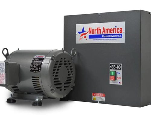
Before diving into the steps, remember that a rotary converter relies on two core components: a control panel and an idler motor. High-quality systems, including the Pro Line series of phase converters, are built to deliver smoother starts and tighter voltage balance.
Step 1: The Control Panel Fires the Start Circuit
The moment you switch the converter on, the control panel energizes a bank of start capacitors. These capacitors deliver an immediate torque boost that forces the idler motor into rotation.
At this point, the unit is not yet producing usable three-phase power. Instead, it is building the magnetic groundwork needed to generate the third leg.
This burst of energy is short, powerful and essential. Without it, most idler motors would struggle to overcome initial resistance, especially in colder environments or when mounted in tight spaces.
Step 2: The Idler Motor Begins Generating the Third Phase
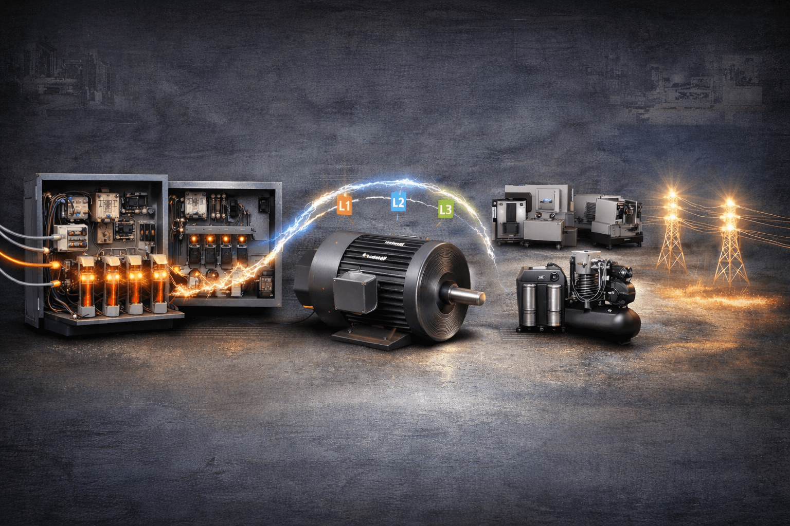
As the capacitor surge hits, the idler motor breaks into smooth rotation. This rotation is what creates the artificial third phase. The idler doesn’t power any machine directly. Its job is to act as a rotating transformer that forms L3, the generated leg.
When the motor reaches its operating speed, the converter becomes a functioning three-phase source.
If you want a real-world example of well-designed idler assemblies, you can see them in the Pro Line phase converters.
Step 3: Run Capacitors Balance the Output
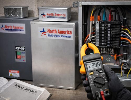
Once the idler stabilizes, the control panel removes the start capacitors and transitions to its run capacitor bank. These run capacitors are responsible for balancing voltage across L1, L2 and L3.
A well-balanced converter protects motors from overheating, torque loss, nuisance tripping or irregular RPM.
This balancing process continues every second the converter is running. The better the balancing design, the more stable your equipment will operate.
Step 4: The Converter Responds to Load Changes
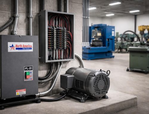
When you power up a machine downstream, the rotary converter reacts immediately. You may hear a subtle change in the idler motor’s tone as the system compensates for load demand. Rotary units shine in applications that involve sudden torque spikes because the idler motor’s rotating mass helps absorb fluctuations.
Shops running compressors, mills, lathes and saws often prefer rotary converters for this reason. The response is natural, fast and consistent.
Step 5: The System Achieves Three-Phase Stability
Once the idler is running and the voltage is balanced, the converter reaches its steady-state mode. At this stage, it supplies clean, usable three-phase power that closely resembles utility-grade output.
This allows industrial machines to run reliably even in locations where true three-phase service doesn’t exist.
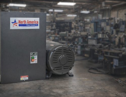
For users looking for stable performance, the Pro Line phase converters represent one of the strongest options due to their build quality and voltage regulation.
What happens during rotary phase converter start-up is a structured electrical sequence:
- the start capacitors force the idler into rotation
- the motor generates the new phase
- the run capacitors balance voltage under load
This is why equipment designed for factory three-phase can operate in garages, farms, and small shops without utility upgrades. Understanding this process makes it easier to choose the right converter and get the most from your machines.